The Octane Node Editor for Cinema 4D
About this Guide
This guide is broken into four parts.
Part I covers the the basics: How to access the node editor, navigate around in it, make nodes, etc. Unless you're brand new to a node editor, you probably know some of this, but it still helps to skim through it and see if there's anything new.
Part II breaks down the nodes into groups and explains how they work together. If you’re already very familiar with the node system, skip to this section.
Part III has two step-by-step walkthroughs, a basic one and a more advanced one.
Part IV gives you a list of things to keep in mind while using the node editor to avoid being overwhelmed or paralyzed.
Intro
Octane Render for Cinema 4D allows you to edit materials and objects in two ways. Traditionally in Cinema 4D, you use a Material Editor or Attributes Manager window to edit the material’s parameters. You’d either click the material in the Material Manager and change parameters in the Attributes Manager, or double-click the material to pop open the Material Editor window, and then do your edits there. This is great for simple changes like altering colors, but once things get more complicated and you start layering up effects, constantly going up and down levels gets confusing and cumbersome.
This is where the Node Editor comes into play. In the node view, a material or object is broken down into smaller chunks, and those chunks are strung together with connectors. This system gives you a flat, visual map of everything that makes up your material or object, and allows you to quickly focus in on the area you want to modify. It also makes it easier to reuse a texture or effect across different parts of an object to cut down on clutter and redundancy.
Everything you change in the Node Editor changes in the material editor/attribute manager and vice versa. It’s the same information, represented in a different way.
Part I: Interacting with the Node Editor
How to access the Node Editor

The Node Editor is available for any Octane material through the Material Editor or Attributes Manager via a button that says “Node Editor”. If you’re using the Attributes Manager, it’s in the upper left corner near the material preview. If you’re using the Material Editor, it’s in the Basic tab.
It’s also available for most Octane objects or tags via an icon with little squares and a connector that’s located next to the Help icon in the Attributes manager.
As of Octane 2020, the Node Editor is mainly used for editing materials, but some objects like the Volume/SDF, Environments and Lights have exposed parameters in the Node Editor which let you create interesting effects. Others like the Camera tag and Octane Object tag have no exposed parameters, so there isn’t much point in going into the Node Editor for these.
When the new AOV system is fully implemented in the 2021 release, the Node Editor will be the best way to create complex AOV systems.
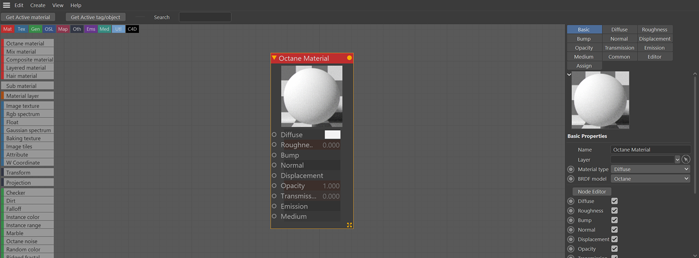
Anatomy of the Node Editor
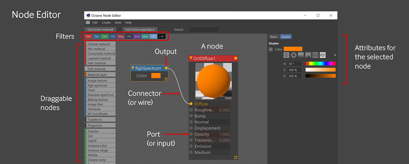
In the middle is a light gray node graph area which is where you create and connect nodes. On the left is a scrollable list of available nodes that you can drag out into the node graph area. At the top are small colored boxes that you can use to filter the available node list by category. On the right is an attributes manager window that lets you adjust parameters for the selected node.
Navigating
You can pan and zoom around in the Node Editor, either by using middle mouse button for panning and alt (or option)-right mouse button for zoom, or holding the 1 key and dragging around with the mouse for pan and the 2 key and dragging up and down with the mouse for zoom. 2-finger drag up and down with the trackpad or scrolling with the scrollwheel in the main Node Editor area (not the part with the list of nodes) will also zoom. If you lose track of where you are, you can go to the View menu in the Node Editor and select Frame All, or hit H on the keyboard.
You can scroll the list of nodes on the left by grabbing it with the middle mouse button and dragging up and down. Two-finger scrolling on a trackpad or the scrollwheel on a mouse works here too if you’re not using a 3-button input device.
Creating new nodes
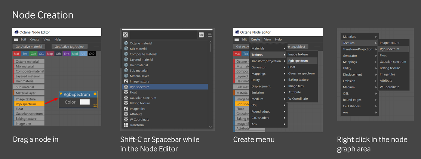
There are a lot of ways to create new nodes. The most obvious one is to grab a node from the list on the left and drag it into the Node Editor window area somewhere. You can filter this list by turning on and off categories by clicking the little colored boxes in the top left. You can also use the search box at the top to filter the list if you know the name of the node. Make sure you clear the search box and/or turn back on all the tabs at the top once you’re done.
As you become more comfortable with the names of the nodes, you can search for them either by hitting Shift-C or spacebar while you’re in the Node Editor.
If none of those methods work for you, you can also right-click anywhere in the Node Editor and pull up a list of nodes.
Still not enough? You can go to the Create menu at the top of Node Editor and pick a node from there as well.
You can also start at an output port and draw a connector into light gray node graph area and drop it and you’ll also get a list of nodes that can connect there.
You can duplicate existing nodes by selecting them and control-dragging them, or hitting the copy/paste keyboard shortcut.
Connecting nodes
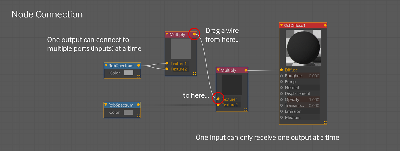
To connect the nodes together, click the little orange-yellow dot (the output) in the upper right corner of a node and drag a line (called a wire or connector) from it to an open circle on the left side of another node (called a port or input).
Most of the time this will work, but sometimes two nodes just can’t connect to each other. You’ll learn later in this guide which one connect together.
The output of a node can connect to the inputs of several nodes. This means you can use a single texture to drive several different channels in a material at the same time.
Each input port on the left of a node can only receive one connector, however. Some nodes allow you to add more input ports if you want to combine the output of three or four nodes.
You can drag from the node list on the left directly into an open port on the Material (try it with an RGB Spectrum into Bump), and it will create the new node and connect it.
If you want a node to sit between two existing nodes, you can drag a node from the left and drop it on the wire, and it will put it between the two. Try putting a Color Correction node between the RGB spectrum and the Albedo.
If you want to disconnect nodes, double-click the wire, or drag a wire out of the port it’s connected to (the right-hand side of the connection) and drop it into the ether.
Organizing Nodes
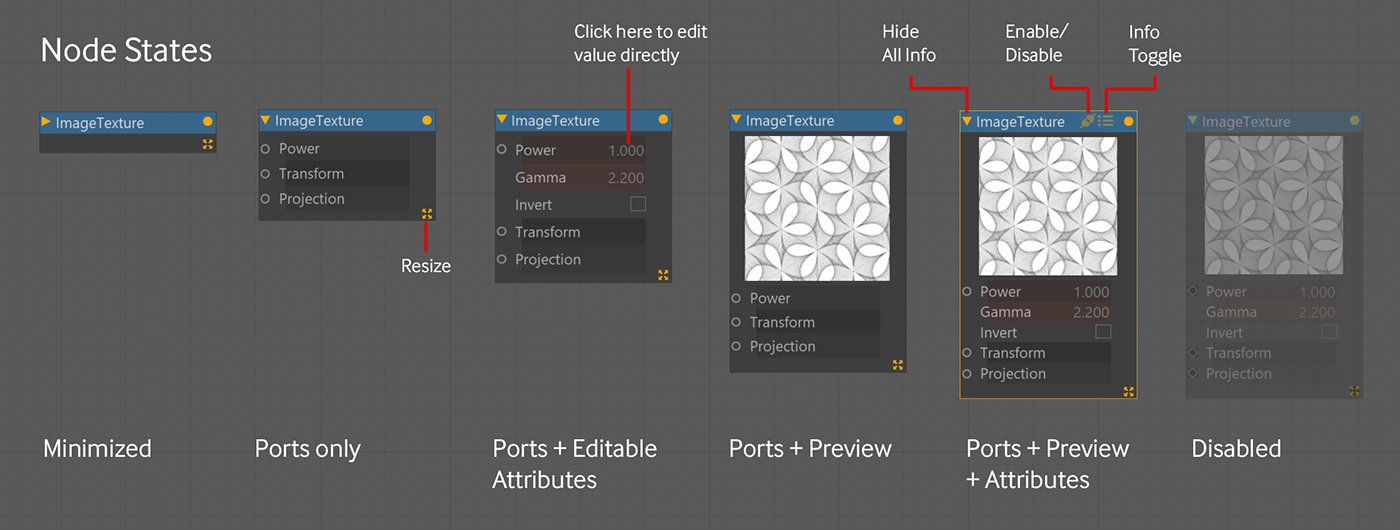
As your node graph gets larger, you might want to minimize some of the nodes to reduce visual clutter.
Double-clicking in the colored titlebar of the node will also expand and collapse some of the info. The little yellow triangle to the left of the name does this as well.
If you single-click in the titlebar of a node, you’ll get icons for enabling/disabling the node and toggling on or off the editable attributes in the bottom part of the node. The editable attributes are exactly that - you can click in the value field and edit it right there. Note: If you toggle either the visibility or the editable attributes too quickly, Octane will read this as a double click and will collapse the node.
You can also grab the little yellow 4-way handle at bottom right of any node and quickly resize it, or grab any edge and resize it.
If you right-click a node you have the option to disable or enable the preview. Previews can slow things down when doing a lot of quick lookdev, but they also provide a very helpful visual indicator of what your node graph is doing at that point, so toggle them on and off as needed.
If you left-click drag a box around a few nodes, you can move them around. You can’t shift, alt or control-click a node to add it to a selection, but you can shift-drag another box that intersects a node to add it.
If you select a group of nodes, you can right-click and choose Auto-arrange. This has varying levels of success, but usually it will take a messy graph and give you a good starting point for reorganizing it.
If you select any node, you can click the basic tab in the attributes manager on the right and rename it.
Disabling a node removes any contribution of that node from your material until you turn it back on. You do this by clicking the little plug icon in the right hand side of the titlebar (appears when you click the titlebar).
Grouping Nodes
If your graph starts getting too large and unwieldy, you can group several nodes together by left-click dragging a rectangle around them, then right-clicking one of the nodes and choosing “Group Items”. If you right-click a group node, you can choose “UnGroup Items” to expand it back out.
Editing the Node Editor
There are a bunch of options available for customizing the Node Editor. Some of these are found under the Edit menu, and the rest are in the Octane Settings, in the Settings Tab in Nodes (a shortcut directly to those settings is found in the Node Editor’s Edit menu>Settings).
Part II: The Nodes
General Workflow

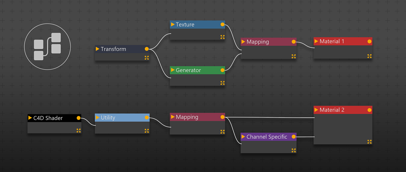
An Octane node network (or tree, graph, or chain) reads left to right in C4D. When two nodes are connected, the node on the left drives an attribute in the node on the right.
Only certain nodes can drive other nodes. Octane will not let you connect nodes that don’t work together. Luckily, you can tell what’s likely to work by understanding the categories the nodes are in. To make this easier, nodes are color-coded.
In most cases you’ll have a dark blue-gray Transform or Projection type node on the far left. These can modify source-type nodes (mostly blue textures and green generators). These source nodes will then feed into magenta Mapping type nodes which make nondestructive instances of the source nodes and let you mix or modify them. Then the results of the mapping nodes (and/or the unmodified source) are fed into various channels in the material or object node on the far right, which is a representation of your final material or object. Some channels require special channel-specific nodes to work - these sit between the source/mapping nodes and the material node.
Categories of Nodes
This guide won’t go over every node, it’ll just point out the more common ones in each category. If you want information on each node, check out the manual in the “Using Textures” section.
The node groupings below are what’s found in Octane Render 2020.2.5. While the general workflow will likely stay the same in future versions, the nodes themselves and how they are categorized may change.
One more thing to note is that some of the nodes are Octane-native. This means they’re unique to Octane and tend to be very stable and versatile. Octane’s Node Editor allows for other types of nodes, however. The light blue OSL and black C4D nodes are not native, but Octane can use information generated by them with varying levels of success. Whenever possible, it’s always best to use Octane-native nodes.
Material Nodes (red) or Object Nodes (indigo)

This is the node representation of a material or an object. As a rule, every material or object can only have one of these (the one exception being the Mix Material).
Most of the time you’ll be using an Octane Material node - this can be made into a Diffuse, Glossy, Specular, Metallic, Toon, or Universal Material in the Basic tab in the Attribute Manager off to the right.
If you are editing a material, and you drag in a new Material node from the left, you are literally creating a new material (look in the material manager - a new one will appear). If you delete the material node, you will delete your material. Again, look in the material manager, it’ll be gone. This behavior seems confusing at first, but we’ll go into it more in Part III when we walk through editing multiple materials in the same window.
Composite and Layered materials use Submaterials and Material Layers as inputs rather than other Octane materials. This is a pretty complex subject by itself and is covered in detail in the Material Layering and Mixing Guides.
Texture Nodes (mostly medium blue)
These nodes and the green generator nodes are what provide most of the source data for your node networks.
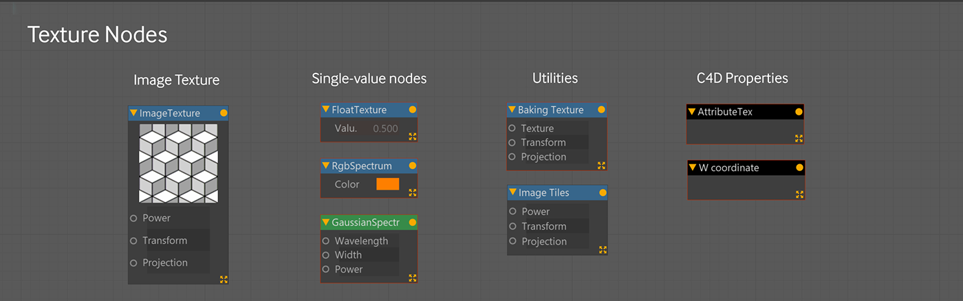
The most common one in this section is the Image Texture node. This is an Octane-native container that holds bitmap images (PNG/JPG/TIFF/EXR/etc). While you can use black C4D-native Bitmap nodes to hold images, they are not anywhere near as versatile as the Image Texture node, and they cause problems when trying to use them with things like an HDRI environment. General rule - if you want to use a bitmap image in Octane, use an Image Texture node.
You can either drag in an Image Texture node and find your image through the popup window, or you can navigate to your image files in Windows Explorer or the Mac’s Finder, and drag them directly into the Node Editor that way. This will create Image Texture nodes for those automatically.
There are also some nodes in this category that create a single value (or a constant). The Rgb Spectrum node and Gaussian Spectrum node (yeah, it’s green, but it’s still in this group) produce a single color. RGB uses RGB values and is good for coloring the albedo channel or creating a gray to mix in with a bump or roughness map. Gaussian uses physical light properties like wavelength to create a color - it’s a better way of working with emissive textures if you can wrap your head around it. The Float node produces a single numerical value. Not overly useful on its own, but good when you’re building out mathy node networks and want a constant that can drive several values at once.
There are also black C4D-native nodes here that have specific attributes of C4D objects that you may need to access.
Generator Nodes (green)

These are Octane-native nodes that mathematically generate image data. These are going to sit in a similar location to Texture Nodes on your node graph (usually on the left of the chain).
There are a few patterns here like Checker and Marble, some noises like Octane Noise, Turbulence, and Ridged Fractal, and then others that generate data based on the geometry like Dirt and Falloff. Some of them overlap functionality, for instance you can choose Turbulence as a noise type in the Octane Noise node, but you won’t get access to the extra inputs on the left (Power/Offset/Lacunarity) that the Turbulence node has if you want to drive those using other nodes.
There are also three nodes that use data from a cloner/scatter/particle system to affect different instances. These affect specific pieces of specific systems, so be sure to consult the manual if something isn’t working the way you expect when you hook these up.
Transform & Projection Nodes (dark blue-gray)
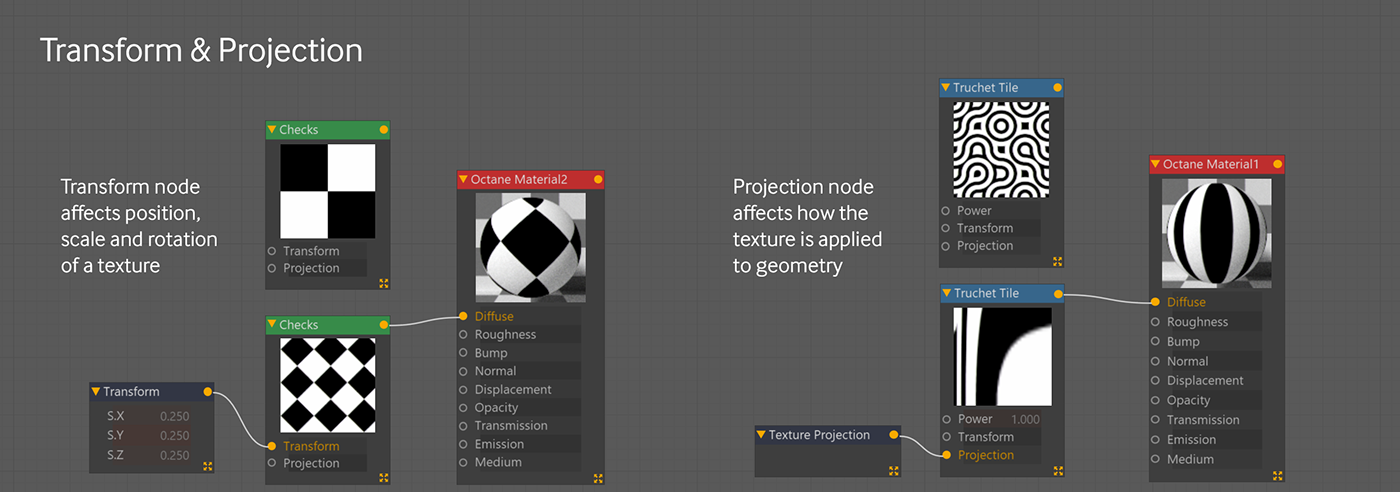
These two nodes are under the Other category and are dark bluish gray. They sit to the left of a Texture or Generator-type node and plug into the appropriate ports. The UVW Transform (magenta Mapping-type) node will accept them as well. Transform lets you change the position/scale/rotation of a texture, and Projection allows you to change how it’s projected on geometry. Each texture can have its own projection to create some interesting effects.
Mapping Nodes (magenta)
This is where the magic happens in the Node Editor. These nodes are not used to generate textures (that’s what the blue and green nodes are for). Instead they’re used to nondestructively mix and modify texture nodes.
The Octane Gradient is simultaneously one of the most used and least understood nodes in the arsenal. The one key thing you have to remember about it is that it’s a mapping node. It’s not a generator, and it’s not a texture. This means it’s not meant to be used to generate a gradient, as weird as that sounds.
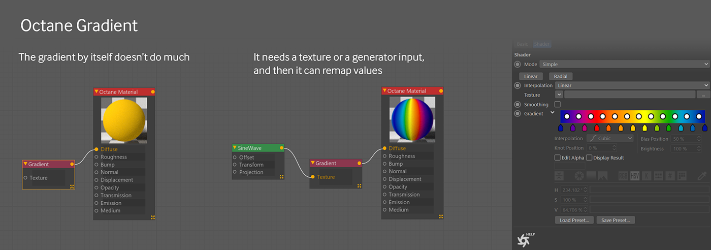
Try this. Make a new material and apply it to a sphere in your scene. Open the Node Editor, and create an Octane Gradient and draw a wire from its output into the Diffuse channel of the material. Select the Octane Gradient and twirl down the arrow next to where it says Gradient in the attributes editor. Choose a rainbow gradient.
The Sphere is a solid yellow, not the rainbow you’d expect. It needs some sort of source data to modify. Now take a green Sine wave generator node and plug it into the Texture port in the Octane gradient. This is more what you might have expected. The generator is generating grayscale texture data which is applied to the sphere. The mapping node (Octane Gradient) is simply taking the grayscale values created by the generator and converting them to colors based on the gradient.
It’s also useful as sort of a Levels or Contrast tool. If you feed in a grayscale image and leave the gradient knots at black and white, but start dragging them in toward the center, it will crush the values and create a higher contrast image. If you flip the black and white knots, it’ll invert the image.
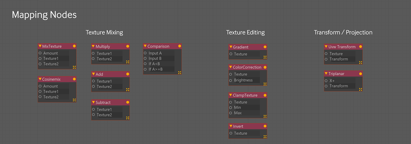
Add, Mix, Compare, Cosine Mix, Multiply, and Subtract are all for mixing textures and generators (and other mapping nodes) together. Most of them simply combine two nodes using a blend mode, but some are a bit more complex. There’s a whole guide on mixing and layering that covers this topic in more depth.
Clamp texture, Color Correction, and Invert are mainly for doing quick edits to a single texture. Some of this can be done in the Octane Gradient as well, but sometimes it’s just quicker to use one of these.
UVW transform is useful for creating several sizes or rotations of the same source texture to mix together or use in different channels or blend together via a texture mixing node.
Triplanar is used to create triplanar projections on geometry - it’s out of scope for this guide.
Channel-specific nodes (gold/purple/teal/orange)
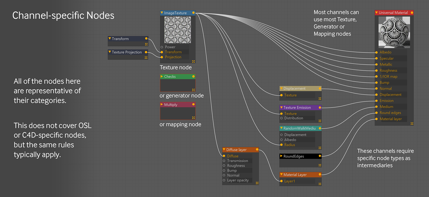
The displacement, emission, medium, round edges, and material layer channels of a material require intermediate nodes before you can connect textures/generators/mapping nodes to them.
If you try to connect a texture/generator/mapping node directly to the displacement, emission, medium, round edges, and material layer inputs, the wire will turn red and it won’t connect. If you go into any of these channels and click “add displacement” or “add medium”, it will create nodes for you, otherwise you can search for them or drag them off the list on the left to connect them to the appropriate channels.
Utility Nodes (light blue)
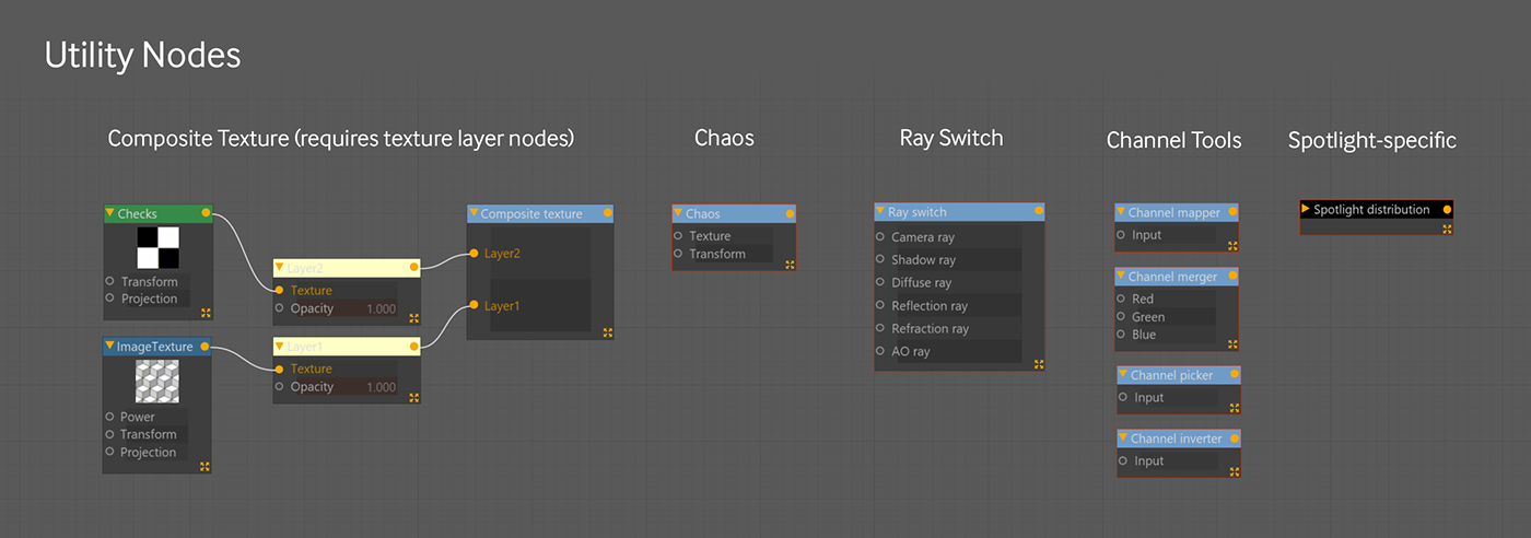
The Utility section is kind of a grab bag of nodes that work sort of like mapping nodes in that they need input from source textures, but they’re for more specific use cases.
The Composite texture node lets you mix several textures together using blend modes, similar to how you would in a 2D image editing application. Similar to a layered material, the composite texture needs composite texture layer nodes to work. This is similar to a Mix/Multiply/Add node, but it’s a lot more powerful.
The Chaos node takes a texture and... well.. applies chaos to it. It’s a lot of fun to play with and creates some really interesting effects.
Ray Switch lets you change the appearance of an object based on various rays (camera/light/etc). It’s pretty technical, but you can do some cool things with it.
The Channel nodes are for isolating and reintegrating channels. Helpful if you need them.
OSL (dark blue)
Octane supports Open Shader Language nodes, which allow you to write your own behaviors programmatically. This is way out of the scope of this guide, but if you’re into writing your own shaders or adapting ones you find on the web, just know that these nodes are here to help with that.
Cinema 4D Nodes (black)
These nodes represent various C4D shaders and utilities. These nodes typically don’t work as well as Octane-native or OSL nodes, and if you have the option of using one of those instead, it’s a good idea to do so.
There are some cases (Mg, or Mograph color shader, Multishader, Vertex Map) where you’ll need these nodes to get specific information, but others like Bitmap, Colorizer, and Gradient that are far better handled through the Octane counterparts.
Note that this isn’t an exhaustive list of C4D nodes - you can drag any C4D object or tag into the node graph from the object manager and see a node representation of it. Sometimes you can do things with these, sometimes not.
AOV Nodes (lavender)
These are for the AOV system, which will be fully implemented in the 2021 release and covered in a future guide.
Part III: Walkthroughs
Building a Simple Node Graph
Create a new Octane material (Diffuse is shown above, but any will do). Click the thumbnail for it in the Material Manager, and use the “Node Editor” button in the upper left to view it in the Node Editor.
The only thing you should see is an Octane Material (material type) node, which is the node representation of the material. On the right hand side of the editor, you have all the same controls that you have in the Material Editor popup window.
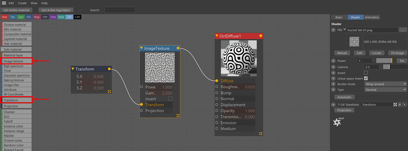
Find the Image Texture (blue texture type) node and drop it next to the Octane Material. When it asks, load in a PNG. Draw a wire from the orange-yellow output circle in the node to the Diffuse (or Albedo) channel in your Material node.
Then drag in a Transform (dark blue-gray other type) node to the left of the Image Texture, and connect it to the Transform input on the Image Texture. Next, click the Transform node, and on the right hand side, set the S.X, S.Y and S.Z values to 0.5. This will scale the texture down 50%.
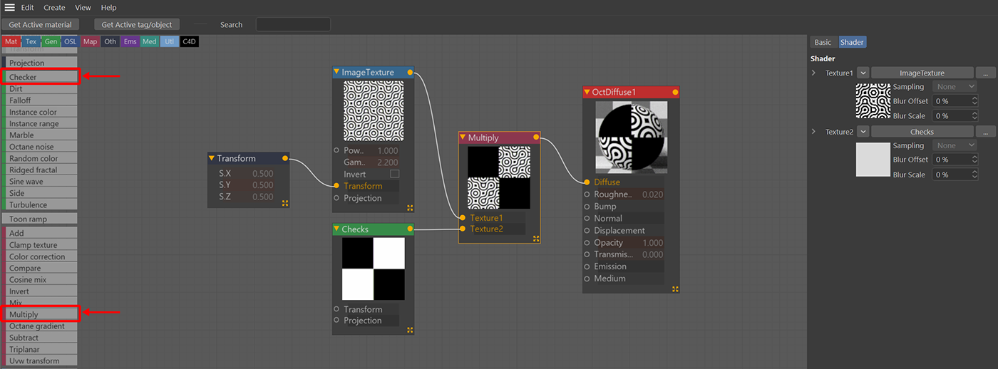
Drag out a Checker (green generator type) node and stack it under the Image Texture. Also drag out a magenta Multiply (mapping type) node. Connect the checker into the Texture 2 Input and the Image Texture into Texture 1. “Multiply” refers to the blend mode, which is the same as you’d find in a 2D editing program. Now connect the Multiply node to the Diffuse channel on the Material Node.
This step starts to show the versatility and power of the Node Editor. Until now, you could have easily built this type of material out in the Material Editor, but now we want the same set of nodes to affect two different channels in different ways. This is possible in the Material Editor, but it’s an annoying and complicated process that gets more difficult and tedious the more complex your material gets. Much easier with nodes.
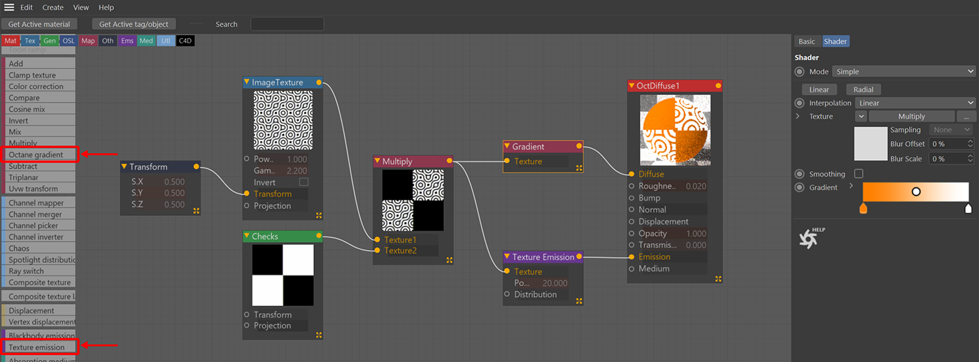
Drag out an Octane Gradient (magenta mapping type) node and put it between the Multiply and Diffuse to recolor it. You can drop it right on the wire and it should hook it up for you. Click the left gradient knot and set it to an orange. Remember, the Octane Gradient is a mapping node. Anything originally black will now be mapped to your orange color, and anything originally white will remain white unless you change the right-hand knot in the gradient. Any shade of gray between will map somewhere along that gradient.
Finally, let’s give it some Emission. Since we read this guide pretty carefully (right?), we know that we can’t just plug the multiply node into the Emission Channel. We need an intermediary node there, so let’s drag out a Texture Emission node and plug it into the Emission channel. Now we can connect the Multiply to the Texture input of the Texture emission, and it will drive both channels at the same time. You’ll probably want to edit the Texture Emission node by selecting it and choosing “Surface Brightness” in the Attributes manager on the right and knocking the power down.
There we go, a reasonably simple material created in the node editor with very little pain.
Editing Multiple Materials at Once
One interesting thing about the Node Editor is that you can actually edit several materials at once in it. This allows for some powerful actions like being able to quickly copy nodes from one material to another, but it takes some getting used to.
If you are editing one material in the node graph, you can drag a second one in from the material manager. Be careful - this isn’t a copy of the material, it actually is the material. If you delete or remove a component from this material from the Node Editor, it will modify or delete the material permanently.
You can also drag new Octane Material nodes in from the left and it will create brand new materials in the Material Manager as well. Again, if you delete these, it will delete the actual material.
Let’s take a look at how this works:
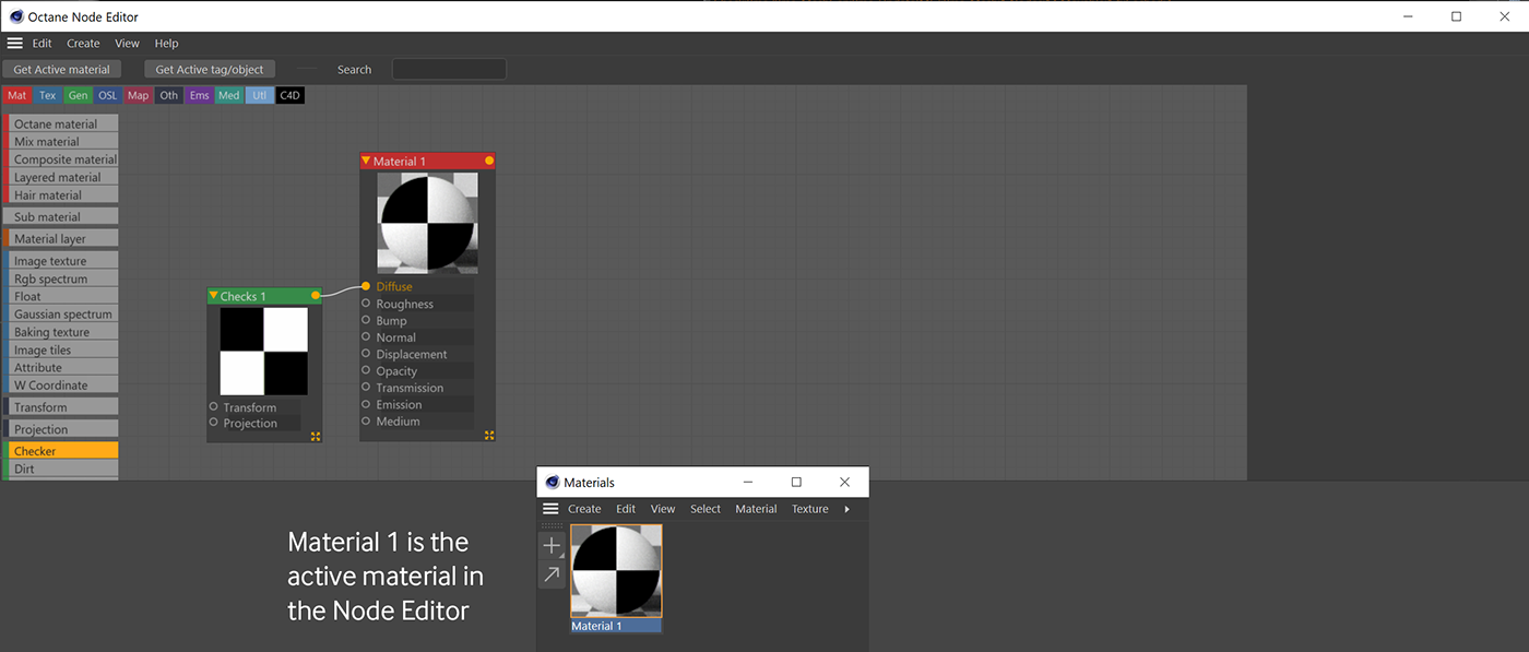
Create a new diffuse material and open it in the Node Editor. Drop in a Checker node and hook it up to the Diffuse Channel. Everything done here is associated with Material 1, since it’s the active material.
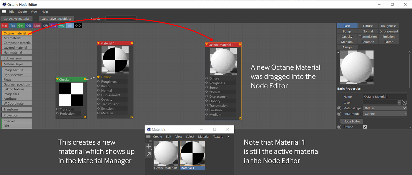
Drag in another Octane Material from the list on the left. A new material will form in the Material Manager. You now have two separate materials, and you’re editing them both at the same time. Material 1 and the Checkers are still associated with Material 1. The Material 2 node is its own thing.
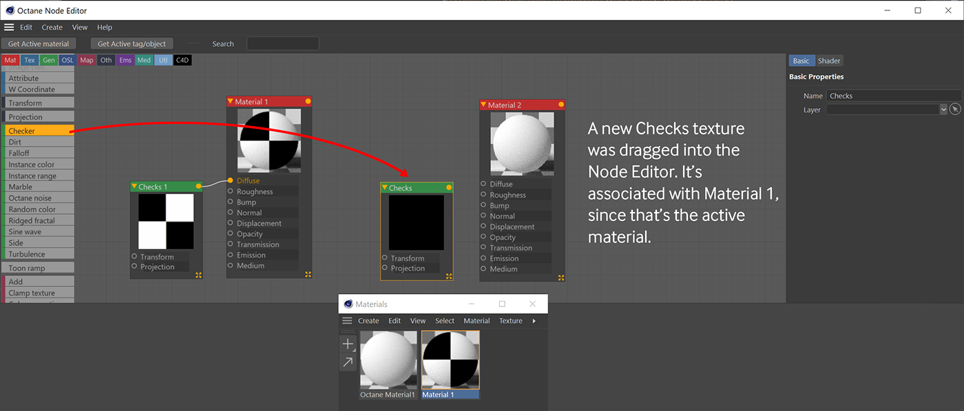
Now drag out a new Checker node. Since Material 1 is still the active material, the Checker node is associated with Material 1, not Material 2. If you were to refresh the node editor, Material 1 would have the three nodes on the left, and Material 2 would still just be the red Material node and nothing else.
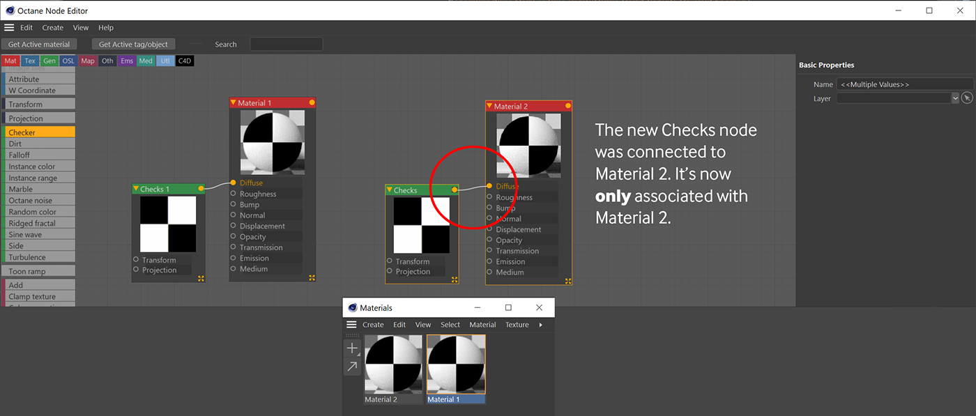
Once the second Checker node is connected to the second material, it switches to become part of Material 2, and is no longer associated with Material 1. If you were to refresh now, the two nodes on the left would be part of Material 1, and the two on the right would be part of Material 2 - let’s have a look at this.
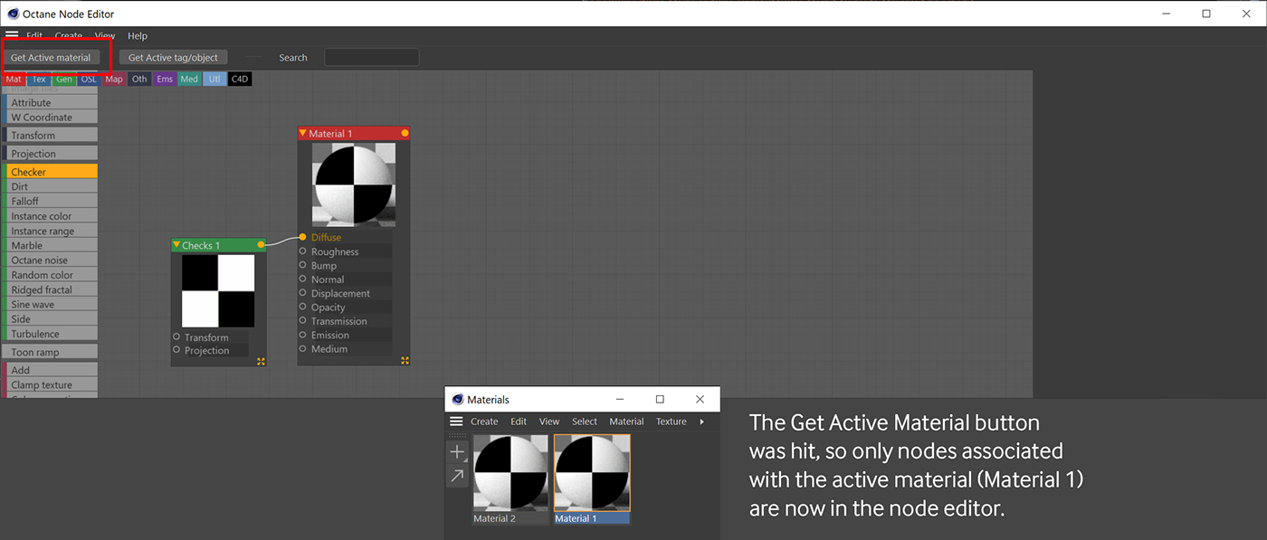
If you hit the “Get Active Material” button at the top of the Node editor window, Material 2 and the second Checker texture disappear from the window. Get Active Material only pulls up the nodes associated with the material that’s active in the Material Manager.
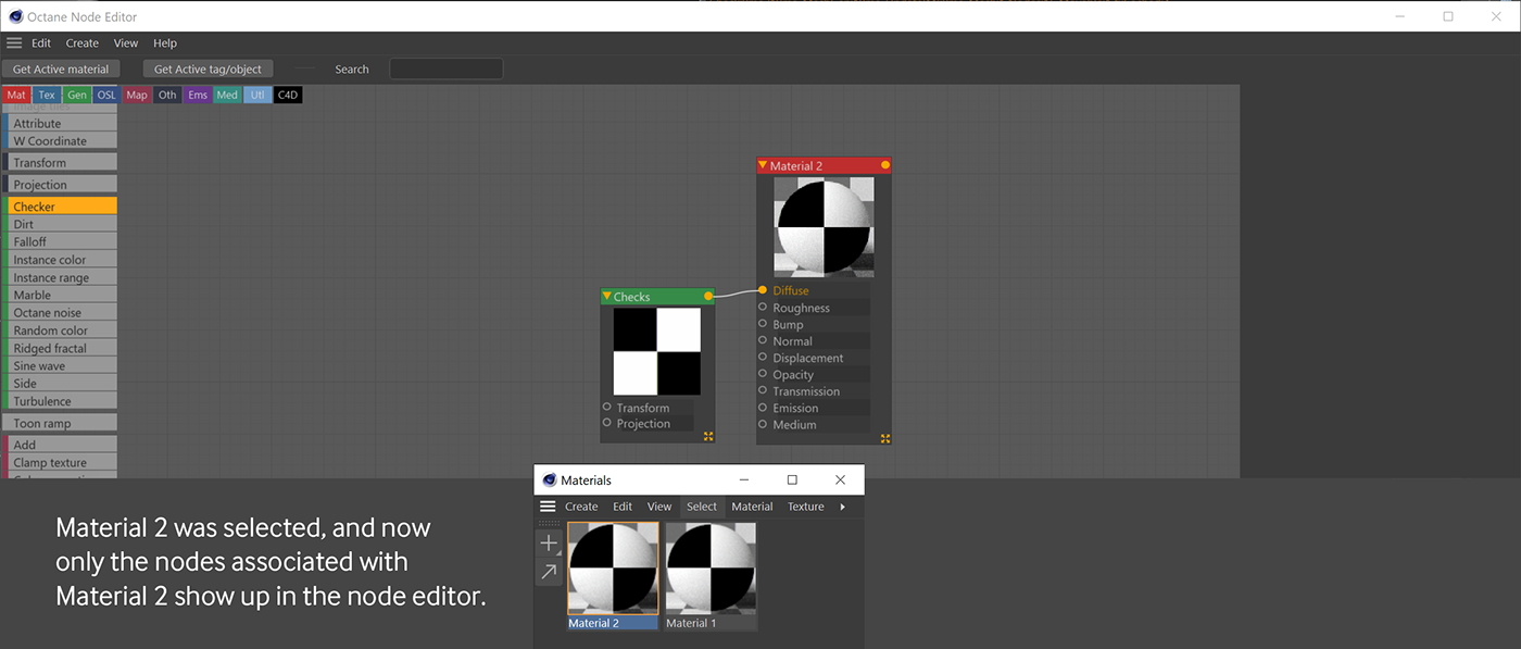
If you switch to Material 2, you’ll only see the Material 2 node and the Checker node that was hooked up to that.
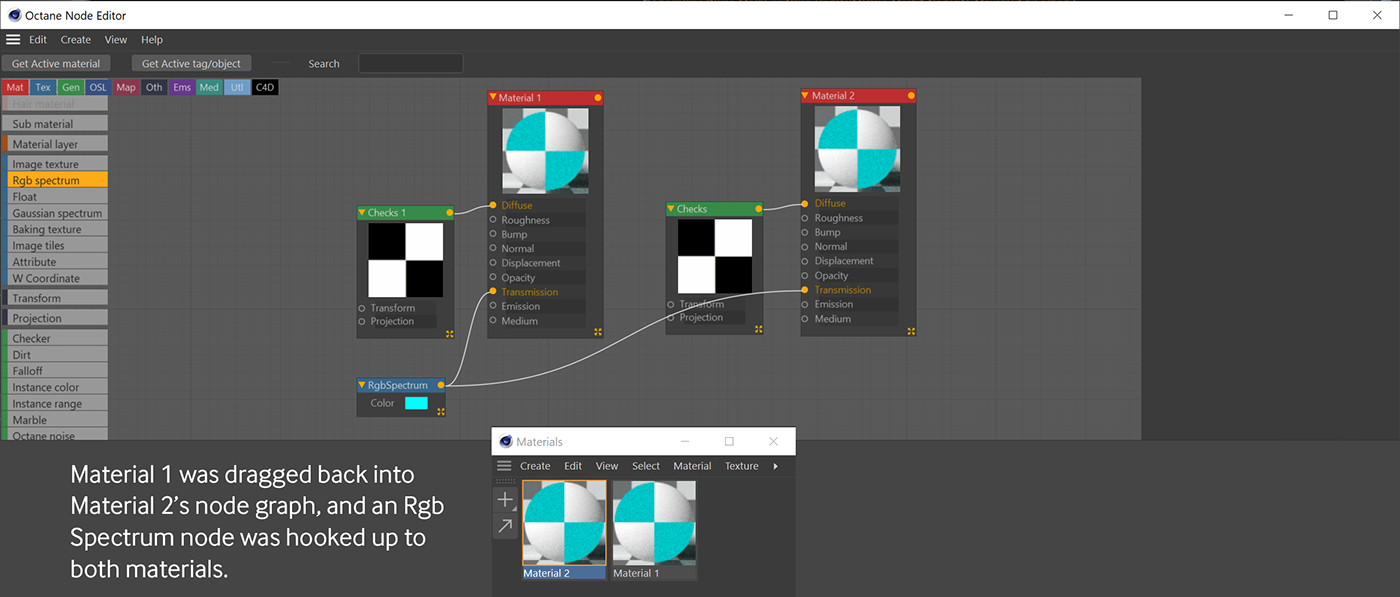
If you drag Material 1 back into Material 2’s graph, both materials will be editable again in the same window. Bring in a new RGB Spectrum node and make the color blue (H:180, S:100, V:100). The new RGB Spectrum will start out associated with Material 2 only, since that’s the active material right now. If you hook it up to a port (let’s do Transmission) in both Material 1 and Material 2, however, both materials will now have copies of that node.
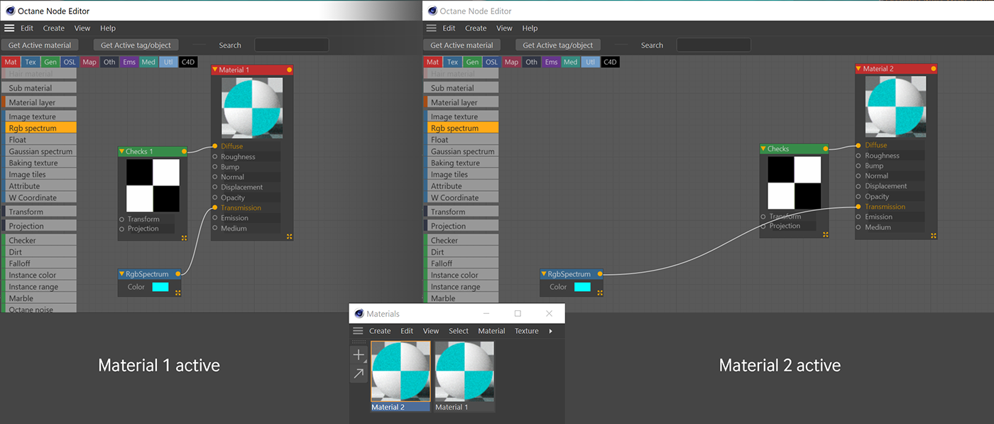
If you toggle between the materials, you’ll see that the RGB Spectrum was copied after it was hooked up to both Material nodes. You can also copy nodes from Material 2, switch to Material 1 and paste them in, but sometimes it’s handy to modify two materials at once if you’re auditioning colors or patterns or something.
Part IV: Things to Keep in Mind
Here are some good practices to keep in the back of your head when working with nodes so you don’t get overwhelmed
Left to right
Nodes on the left modify nodes on the right. Usually transform and projection is the furthest left on any branch, then the source (texture or generator), which are mixed and modified using the magenta mapping type nodes, and then all that is fed into the various channels of your material.
Reuse nodes

This is one of the Node Editor’s superpowers. Reuse as many nodes as you can. You can always put in mapping nodes further downstream to create different versions of the same base texture or generator for different purposes. This makes it much easier to swap out a texture later if needed and keeps the number of nodes down in your graph.
In the example above, one single texture is modified in three different ways via the UVW Transform (Mapping type) node, and then recombined using Multiply and Add (Mapping type) nodes to form a complex pattern. The combined pattern is then fed into the diffuse, bump and opacity channels. All you’d have to do is change out the png in the Image Texture node and modify the values in the transform nodes to audition different looks.
Keep organized
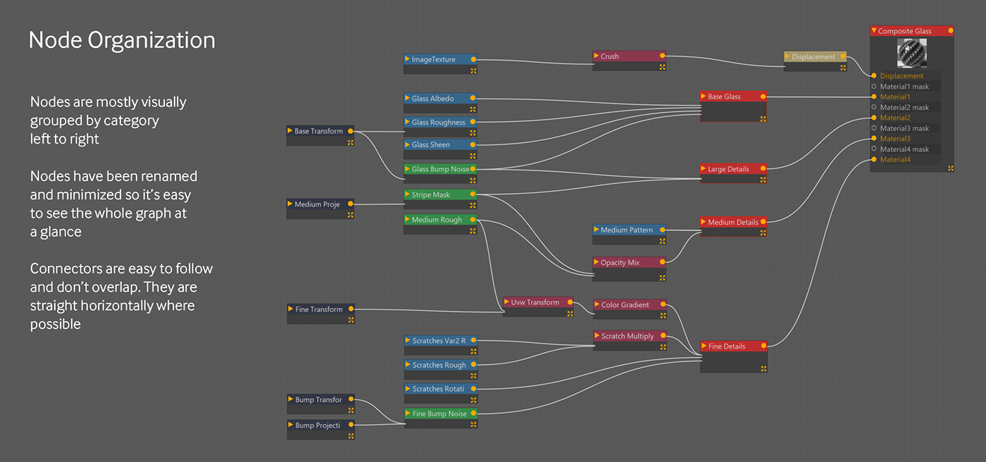
This is probably one of the most important aspects of working in 3D, and especially so when you’re creating complex node networks. Think about coming back to the material two months later to edit it, and consider what your future self (or someone else looking at your file) would want to see in order to be able to modify it easily.
Watch your wires - try not to cross wires if possible - it doesn’t affect how anything works, but it’s much easier for your eye to follow if things are straightforward and orderly. Sometimes it’s unavoidable, but most of the time you can just rearrange the nodes. Making wires as horizontal as possible makes them easier to follow and it just looks better.
Utilize the organization tools - use the align tools (right click after selecting a few) and the auto-arrange tool (View menu in the Node Editor).
Name your nodes - in the Basic tab of every node, you have the option to name your nodes. This can be helpful if you have several of the same mapping node in a row. If you combine renaming with minimizing nodes, you can have a ton of them on your graph and easily be able to tell what’s what.
Minimize nodes - shrink them down (double-click the node’s title bar, resize, use the little icons in the upper right of the title bar) to only what you need to see if you’re starting to get overwhelmed. If you name them appropriately you can still easily follow your thought process.
Use groups - select a bunch of nodes, right-click and choose “Group items” - this will clean up the Node Editor. Unlike Octane Standalone, you unfortunately can’t then dive into a group in a different tab, so you’ll have to ungroup them to make any edits.
Simplify
When something isn’t working as expected, disable/disconnect nodes or duplicate the material or object, isolate one channel or node branch at a time and build it up piece by piece to see what the issue is.
Even if nothing is wrong, sometimes giving your network a closer look and breaking the parts out and thinking through them individually will reveal better ways of achieving the effect you’re after with fewer nodes.
Reverse engineer materials
Go find or buy a bunch of Octane materials, and then open them up and see how they were made. What you find there may not be best practices, but they might give you some ideas when constructing your own materials. Rip them apart and disable or disconnect portions to see how a specific effect is achieved, and steal and reuse those processes for your own materials.


